Phy home life
DIY Digital FM Radio Soldering Kit
DIY Digital FM Radio Soldering Kit
Couldn't load pickup availability
Product Features
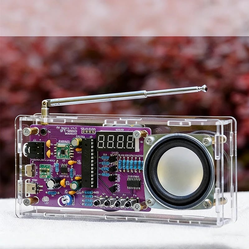
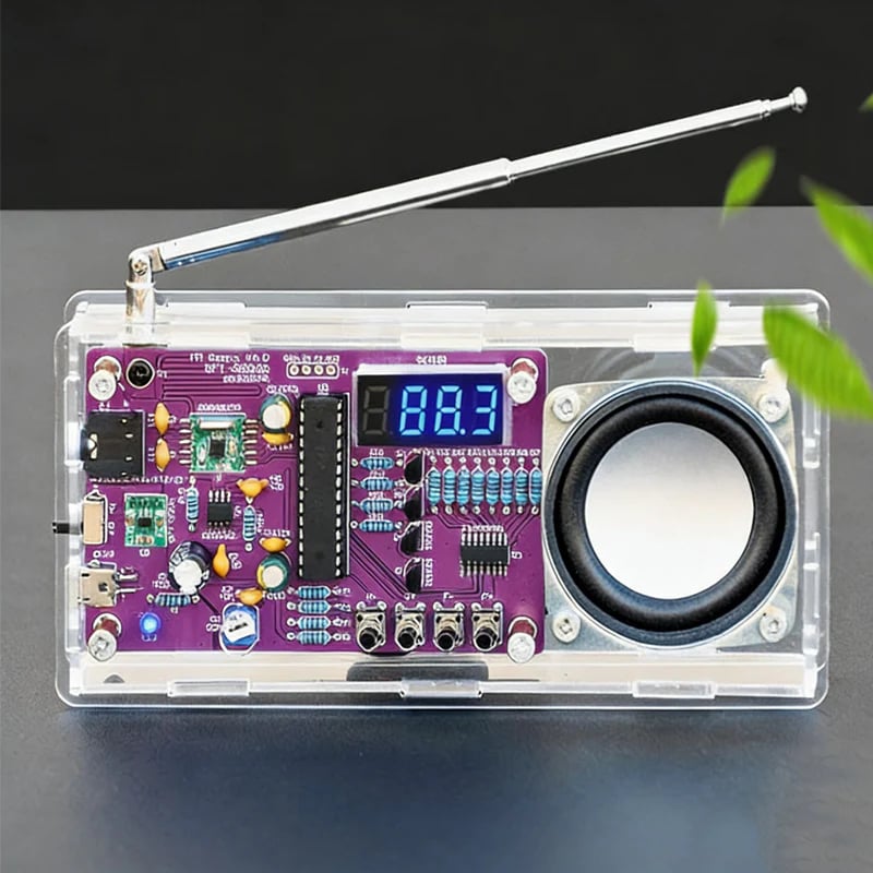
Voltage Regulation Circuit: Incorporates a 3.3V buck-boost module to maintain stable voltage supply to the microcontroller and digital display. The system remains functional with input voltage as low as 2.5V.
Audio Amplification: Uses an AXS2031 digital amplifier chip to deliver up to 5W of monaural audio output, designed to reduce distortion at varying voltage levels.
Signal Reception Design: Includes a 30cm telescopic omnidirectional antenna and integrated spiral copper PCB traces to improve FM signal sensitivity across the 87.5‑108MHz band.
Microcontroller Unit: Based on an STC15W408AS MCU with power-off memory function, which retains the last tuned frequency when restarted.
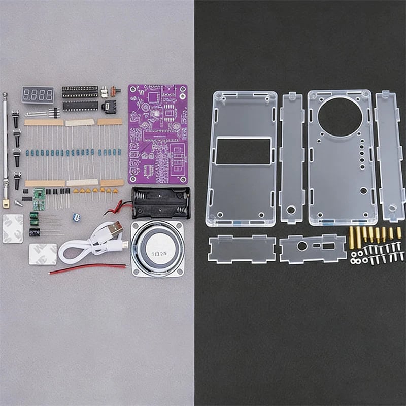
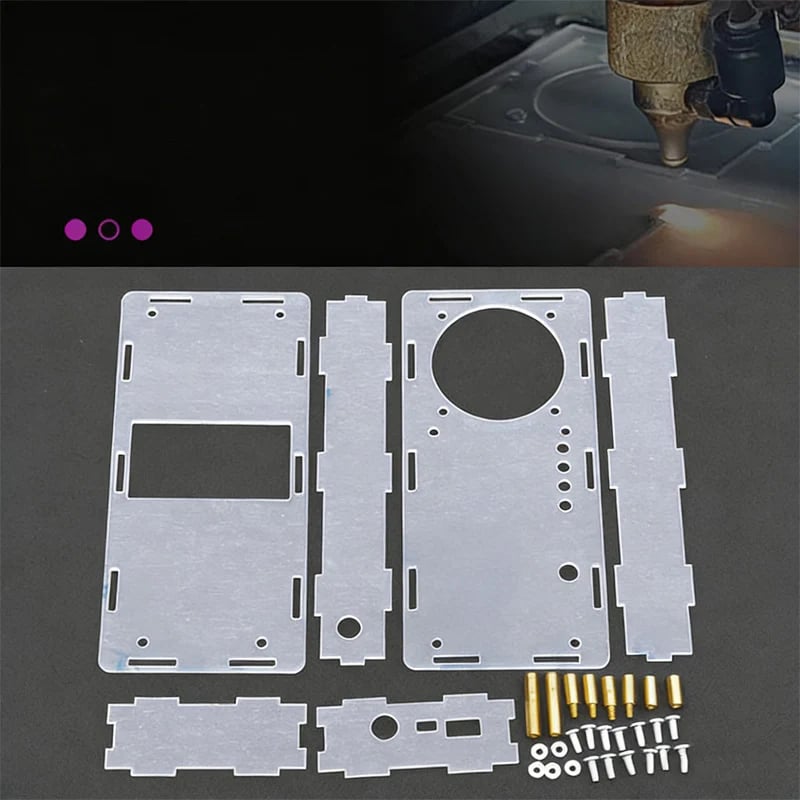
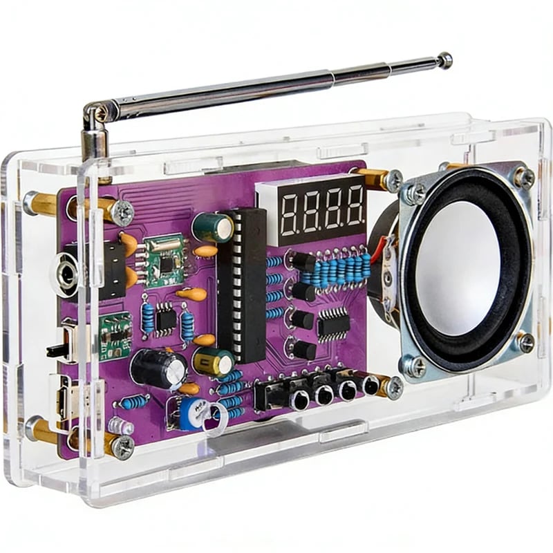
Enclosure Options: Available with a transparent acrylic housing, precision-cut and assembled using copper standoffs, or as a kit without housing.
Specifications
Model Options: Kit Only (No Housing), Kit + Housing, Fully Assembled Unit
Dimensions: 158 × 28 × 74mm
Housing Material: Acrylic with copper standoffs
Operating Current: 10mA
Power Input: 2 × AA batteries or 5V/1‑2A USB power source (use one at a time)
FM Frequency Range: 87.5‑108MHz
Amplifier Chip: AXS2031
Audio Output: 5W monaural
Antenna: 30cm telescopic
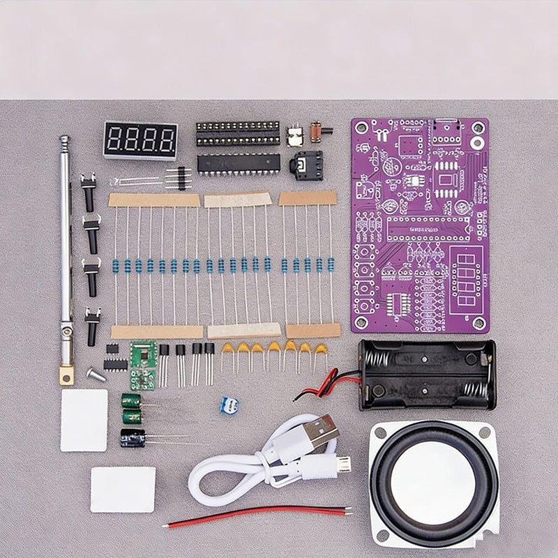
Contents: 1 × DIY Digital FM Radio Soldering Kit (components and PCB)
Assembly Instructions
- Secure the antenna vertically with screws and solder to the PCB.
- After completing PCB soldering, attach the front and rear hex standoffs.
- Install the front, side, and rear acrylic panels in order, then tighten all screws.
Notes
- This is a DIY soldering kit; soldering tools and equipment are not included.
- Only one power source (batteries or USB) should be connected at a time to prevent circuit damage.
- An electronic assembly guide is provided with the kit.